

What are the service life and usage characteristics of current collectors - Yangzhou Darui Co., Ltd.
Darui Electric recommends for you
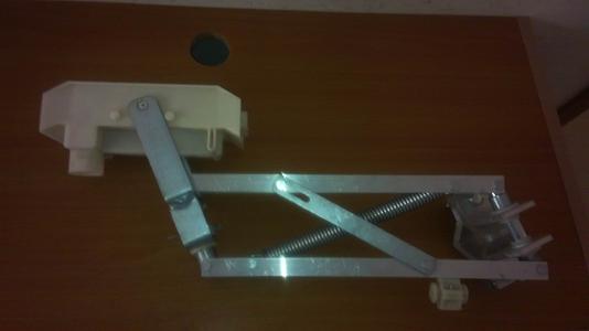
The current collector is a support-type structure and is the main component for supplying power to mobile equipment. It consists of special carbon brushes, terminal posts or terminals, plastic protective covers, and support arms. It applies appropriate contact pressure, slides smoothly along the guide rail, and supplies power to the equipment. When the equipment requires maintenance, the carbon brush of the current collector can be pulled away from the guide rail to cut off power, facilitating the operation.
The current collector is the main device for picking up electrical energy on the current collection side in the sliding contact line system. It directly conducts electrical energy to the electrical appliance through the sliding contact between the collector brush and the guide rail, thereby achieving mobile power supply for the system. It consists of two parts: the tension device of the mechanical structure and the collector brush that directly slides in contact with the guide rail.
The tension device of the mechanical structure determines the sliding contact pressure between the collector brush and the guide rail and the stability of the mechanism. The collector brush is the conductor that slides in contact with the guide rail to pick up electrical energy. Its performance, conductivity quality, and the quality of material structure and composition will directly affect the operating quality of the entire system equipment.
The above is the service life and usage characteristics of the current collector. Welcome to contact the editor to add more.
1. According to the installation schematic diagram, number the conduit, thermal expansion compensation section, disconnection section, arc section, intermediate power supply section, etc., in sequence according to the actual position.
2. Insert the floating suspension clamp and fixed suspension clamp into the conduit with the specified quantity and spacing.
3. When lifting and installing the first conduit, use a fixed suspension clamp to suspend it on the bracket as the baseline for straightening the entire line. After installation, if this section is not used as a fixed suspension section, it can be replaced with a floating clamp.
4. For the first conduit lifted, install the fixed suspension clamp on the bracket, adjust the parallelism with the rail in the horizontal direction and the centerline in the vertical direction, requiring no more than 1.5/1000, then tighten the nut to fix it.
5. Then lift and install the second conduit. In addition to meeting the requirements of the fourth item, ensure the straightness with the first conduit in the horizontal and vertical directions is 1.5/1000.
6. Conduit connection: Different guide rails use different connection methods, as shown in P10. Users should note that regardless of the connection method, an insulating isolation plate must be installed at the joint to prevent the guide rail from moving and contacting the metal shell. After connection, if there are protrusions, unevenness, or non-smooth transitions, open the slot and smooth it with a file or petroleum.
Note: The above information and technical parameters are compiled and released by Yangzhou Darui Electric Co., Ltd.