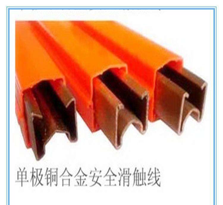

Before installing the sliding contact line, first fix the mounting bracket according to the installation form selected by the user, based on the suspension
spacing of the sliding contact line. At the installation site, slide the required suspension hangers onto each 6-meter or 4-meter section of the sliding contact line, along with one end connector cover for each end,
and also install one connector on one end. When installing the connector, note that only 1/2 of the guide rail of the sliding contact line should be inserted into the connector, leaving the other 1/2 for connection with another guide rail. After the above preparations are completed, hang the sliding contact lines one by one on the brackets and connect them along the entire line. When connecting, tighten the screws of each connector. When the total length of the sliding contact line exceeds 200 meters, expansion sections should be appropriately added. When connecting the power supply wires, connections can be made at the joints of each 6-meter or 4-meter section.
When installing curved sliding contact lines, the installation distance of the collector hangers should be correspondingly shortened.
The specific dimensions can be determined based on site conditions. For installation and maintenance of the sliding contact line, when installing the collector, first mount the collector on the matching square tube, select an appropriate position that matches the sliding contact line, and fix it on the electrical equipment. Note that to ensure good tracking performance and proper contact pressure between the collector and the sliding contact line, the collector and the sliding contact line should be installed in the same vertical and horizontal direction. Before power transmission, conduct a full-line re-inspection, especially the power supply connectors, to confirm they are not loose. After confirming correct installation, follow the debugging personnel to the operation position, then power on. After turning on the power, observe the normal power-on status of the mobile equipment, first start a small-power mobile device and run it for a few minutes, then start a large-power mobile device to run. Observe the left and right deflection of the collector relative to the sliding line along the entire line. If the deflection is too large, adjust the sliding line again. Observe the sliding state of the collector carbon brush when passing through the sliding line connections. If unstable operation or poor contact occurs, reinstall the sliding line interface, or increase the stainless steel chamfer at the end of the sliding line and reinstall, adjusting to a suitable position.
The following parameters must be provided for the selection of the sliding contact line:
Working environment: such as dust, corrosion, temperature, etc.;
Ambient temperature: the highest temperature on site throughout the year, and the lowest temperature for the collector;
Load conditions: load factor, rated power of each load, power factor, and operating conditions of each load;
Installation requirements: space size, installation method (such as trench type or overhead type), operating speed, etc.;
Voltage drop requirements: refers to the voltage loss shared on the sliding line;
Other requirements: signal interference, etc.
Factors affecting the selection of sliding contact line:
Environment (humidity, indoor or outdoor, corrosion, dust, etc.), working temperature, installation space, current-carrying capacity, and voltage