
What standards can be used to measure the quality of sliding contact lines?
Sliding contact lines have two types: combined structure and composite structure. They are supported by high-strength special insulators, which are installed or welded on the brackets of the beam. They form a mobile power supply system for each hoisting equipment. Due to movement, mobile equipment needs to constantly change positions. At each different position, the mobile equipment must be able to obtain power at any time, otherwise they cannot move. At this time, contact lines came into being, with many conductors placed parallel along the execution track of the mobile equipment to supply power. On the mobile equipment, a current collector that can draw power from the conductors is installed. Therefore, as the facility moves, the current collector synchronizes with the facility, and power is drawn from the conductors at any time and supplied to the facility, allowing the facility to continue moving.
Sliding contact lines have advantages such as long service life. The track is made of cold-rolled steel plate formed by one-time cold drawing to ensure the precision of the track cross-section dimensions. Copper busbars replace angle steel and other conductive methods that are unsafe, heavy, prone to dust accumulation indoors, and icing outdoors causing short circuits and affecting use. They also have domestic characteristics. The track uses coupler connectors and can be extended to any length as needed. Sliding contact lines can drive all trolleys to slide freely at any speed in the track. The guide rail is easy to install, requires no debugging, and has the advantages of contactless power supply, safe and reliable.
The quality of sliding contact lines can be measured according to the following standards:
1. Carbon brush service life - it is a consumable item. The quality of carbon brushes varies, with a difference of up to two times. Installation quality, travel distance, and speed affect the maintenance cycle of carbon brushes.
2. Shell quality - applicable temperature, environment, etc.
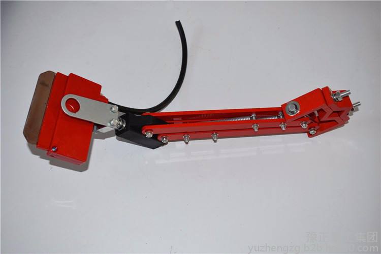
3. Current collector performance - mainly from the service life of wheels, the design of turning wheels, and whether the current collector can be used in various environments.
4. Expansion issue - when the length exceeds 100 meters, expansion must be considered.
5. Voltage drop issue - the voltage drop varies according to the length of different copper bars.
Installation work sequence:
1. Install the angle steel brackets along the track at the preset positions. The spacing of the brackets should follow the standard distance as much as possible, and ensure they are parallel to the centerline of the track.
2. Install the lifting clamps on the angle steel brackets, and set the nuts in appropriate positions to ensure that the lifting clamps can also move left and right on the long holes of the brackets.
3. Install the sliding guide rail from one end of the track, so that the distance from one end to the bracket is as close to 750㎜ as possible.