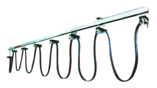

What are the acceptance standards for busbar installation?
Through continuous knowledge learning, we understand and get to know busbars better, allowing ourselves to make progress and gradually accumulate knowledge, so as to achieve the expected learning goals and requirements as soon as possible. Therefore, the following content is no exception, still about the acceptance standards for busbar installation, which we should clearly understand, so that everyone can gain new insights and shorten the gap towards the goals.
1. Brackets
1. Should be treated with anti-corrosion.
2. Should be continuously welded.
3. Installed firmly, with consistent installation hole positions.
2. Bracket spacing
For single-line "H" type below 300A ≤1.5M, above 400A ≤3M.
For multi-line seamless busbar type 1.0-1.5M, conduit type 1.0-1.5M, cable trolley type 1.0-2.0M, and for arc segments, the bracket spacing should be <1.0M according to on-site conditions.
3. Suspension parts
Position correct, installed firmly, quantity meets requirements.
4. Main body of busbar
1. Gap between protective shell and conductor ≤2mm.
2. Straightness: allowable deviation from track center height < ±15mm.
3. Straightness: allowable deviation from track center longitudinally < ±15mm.
4. Twist: <15mm/10m.
5. Expanders
1. Quantity complies with regulations.
2. Gap distance should accommodate the theoretical expansion/contraction amount caused by temperature difference at the installation site.
6. Current collectors
1. The square steel bracket should be welded firmly, with the centerline perpendicular to the busbar, allowable deviation ±3mm.
2. The dimensions between the square steel bracket and the busbar should ensure that the movable arm of the current collector is parallel to the main body of the busbar, with allowable deviation ±3mm.
3. The current collector slides smoothly on the busbar surface, meeting the specified pressure. (See next page: Contact pressure table between collector brush and guide rail)
7. Fasteners
The torque of fastening nuts should comply with the manufacturer's recommended values. Recommended values: M10-28NM, M8-12NM, M6-6.5NM
8. Power inlet
The inlet end should be firm and must not bear tension.
Previous: Comparison of advantages and disadvantages between copper conductor busbars and aluminum conductor busbars
Next: Hydraulic buffer is an essential safety device for elevators