

How to Complete Two Power Supply Action Processes with One Sliding Contact Wire
DARUI Electric recommends for you
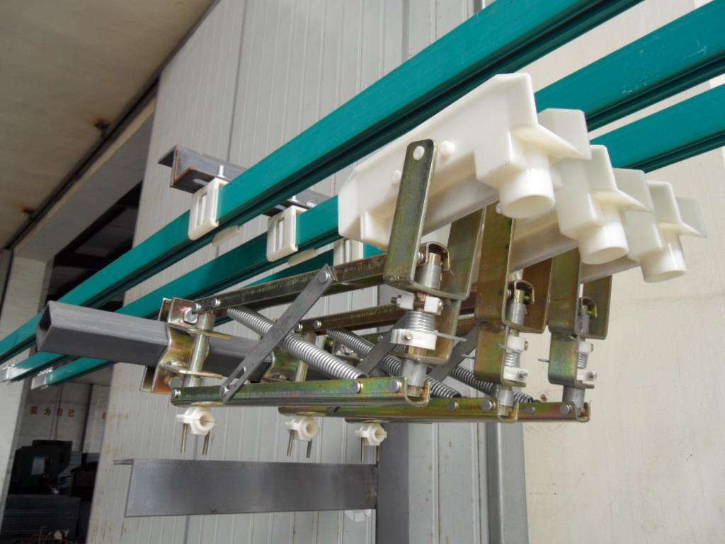
Sliding contact wire safety during use is very important, but often due to various reasons, its safety can be compromised, among which the more common problem is arcing. If arcing occurs, it can cause significant safety hazards, so it must be paid attention to. Next, let's understand how to avoid the problem of arcing in sliding contact wires.
To avoid arcing, first find the cause of the problem. Generally speaking, it is caused by loose connections between the connectors of the sliding contact wire or severe wear of the wire itself. Knowing the cause, you should know how to avoid it. For the arcing problem in the first case, the operator needs to conduct a thorough inspection before use, which can smoothly avoid it. For the second problem, the general approach is to directly replace it.
①When H1 has no voltage, since the primary terminals of transformers TR1 and TR2 are in the same phase, and the secondary terminals are in opposite phases, there is no voltage across the coil of intermediate relay J1, and contactors ZC and FC do not operate.
②When the contacts of intermediate relay J2 close (J3 does not close), H1 is R-phase voltage. TR1 has no secondary voltage output because both ends of its primary are the same R-phase voltage. TR2's primary is R-phase and S-phase 380V voltage, J1 is energized and closes. Since both ends of contactor ZC are the same R-phase voltage, it cannot close; both ends of contactor FC are R-phase and S-phase 380V voltage, contactor FC closes, completing the descent action.
③By the same principle, when J3 closes (J2 does not close), contactor ZC closes, completing the ascent action.
2. Selection of electrical component parameters
①Transformers TR1 and TR2 should be standard control transformers. Considering the small coil capacity of intermediate relays, the transformer capacity can be 1.5-2 times the coil capacity.
②Considering that the secondary sides of transformers TR1 and TR2 need a certain voltage drop, when selecting transformers, choose ones with a larger turns ratio to reduce the impedance of the secondary side. Generally, 380V/24V or 380V/36V is suitable. In the design of electric hoists, any two signals that do not need to act simultaneously can use the principle of phase difference between the same-name terminals of transformers, which reduces the number of wires and thus lowers the failure rate. This method has been applied in our company's electric hoists.
Note: The above information and technical parameters are compiled and released by Yangzhou DARUI Electric Co., Ltd.