

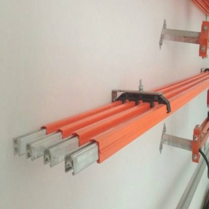
I. Introduction to H-Type Busbar
The HXPnP, R-H type protected crane busbar, also known as the H-type sliding wire device, has a conductive main body made of aluminum profile with an "H" cross-section, hence the name "H" type sliding wire device. Compared to busbars primarily using angle steel, the energy loss during power transmission is greatly reduced. Aluminum has a much lower resistivity than steel and a lower density. Rolling aluminum into an "H" shape ensures overall rigidity and strength based on the maximum conductive cross-sectional area. However, aluminum surfaces have low hardness and are not wear-resistant. To make the aluminum substrate practical as a conductive sliding wire, the "H" shaped middle beam is formed with an upward arch, and stainless steel profiles are embedded at this location following specified process procedures. This "H" shaped stainless steel profile serves as the friction and current transmission surface for the conductive blocks in the current collector. The embedding process ensures a tight combination of stainless steel and aluminum profile. The current from the aluminum profile is transmitted through the stainless steel body to the conductive blocks in contact, which transmit the current through friction contact, ensuring continuous current during crane operation.
The conductive sliding wire is protected along its longitudinal direction with ABS plastic as a whole, except for the lower opening where it contacts the current collector. Therefore, after installation, there is no exposed conductive part on the contact line, bringing great convenience to installation and maintenance. At the same time, the overall plastic shell protection (except for the opening) prevents dust accumulation and protects against rain, dew, ice, and snow. The connection between rails is achieved through a dedicated rail connector that allows both the rail and plastic shell to extend into it, and the connection ends are also specially designed.
II. H-Type Busbar Models and Specifications
III. Main Technical Parameters of H-Type Busbar
Specification
HXPnR-HD2
HXPnR-HD3
HXPnR-HD5
HXPnR-HD8
HXPnR-HD13
HXPnR-HD20
Rated Current (A)
200A
300A
500A
800A
1300A
2000A
Resistance at +35°C (Ω/m)
11.4×10⁻⁵
10.4×10⁻⁵
9.4×10⁻⁵
6.8×10⁻⁵
5.7×10⁻⁵
4.8×10⁻⁵
Resistance between rails at 800mm gauge (Ω/m)
22.2×10⁻⁵
18.2×10⁻⁵
16.5×10⁻⁵
12.0×10⁻⁵
10.1×10⁻⁵
9.0×10⁻⁵
Operating Voltage (V)
600V/A or 600V/DC
Insulation Sheath Breakdown Voltage (KV)
13.9
Insulation Surface Resistance (Ω)
2×10¹³
KC
>600V
Maximum Operating Speed (m/min)
600
Ambient Temperature Range
-25°C+55°C
Flammability of Insulation Material
Self-extinguishing
Dimensions
23.6×31.6
32×42
Suspension Spacing (m)
1.5-3
Rail Section Expansion
Not considered for installation length within 200m
Standard Rail Length (m)
6
Specification
HXPnR-HG150
HXPnR-HG150
Rated Current (A)
150 (double 300A)
250 (double 500A)
Maximum Operating Speed (m/min)
600
Contact Pressure (N)
27
Lateral Movement Distance (mm)
±100
Contact Direction Movement (mm)
±40
Connection Cable (mm2)
20
50
Distance from Traction Arm to Rail Contact Surface (mm)
115
130
Applicable Rail (A)
200-300
500-800
Weight (Kg) (single pole)
1.6
2.2
Note: When selecting a current collector, its capacity should match the electrical equipment. If the capacity of a single collector is insufficient, dual collectors can be used.
IV. Structure and Dimensions of H-Type Busbar
V. Assembly Diagram and Main Components of H-Type Busbar
1. End cap 2. Dual current collector 3. Rail joint 4. Suspension seat 5. Rail 6. Rail sheath 7. Power feeder
Current Collector: It is a spring-supported type. It can be pushed in from the lower part of the busbar, but it must be synchronized with the traction device, and the spring force should be appropriate to avoid excessive wear of the carbon brushes. The traction device and the current collector move synchronously and can be fixed to moving equipment such as cranes using bolts or welding, ensuring that the current collector operates without torsional forces.
VI. Selection Guide for H-Type Busbar
When selecting this busbar system, users should consider the total capacity and duty cycle of the electrical equipment on the same span. The current-carrying capacity curve above is for reference. When selecting a current collector, the capacity of the electrical equipment should be matched. If the capacity of a single collector is insufficient, dual collectors can be used.
VII. Installation Forms of H-Type Busbar
Note: This device is generally installed in a top-mounted or side-mounted manner. Multiple rows and curved sections are allowed (the minimum radius of curvature must not be less than 1.5m). The dimensions in parentheses are suitable for 200-300A rails, and the spacing a between L1, L2, L*E is 90mm.
VIII. Power Supply Methods for H-Type Busbar
When considering the power supply points of the busbar, the total number and total capacity of electrical equipment on the same span should also be considered.