
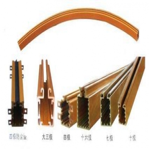
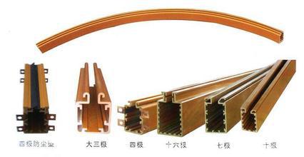
FKC Air-Insulated Busway Detailed Introduction
FKC Air-Insulated Busway
Dary Electric recommends
Product Description:
Performance:
1. The busway that uses bare busbars (for low current applications, I ≤ 400A), or busbars with insulated coating (for high current applications, I>400A), supported by insulating spacers inside the housing, and insulated by air medium, is called air-insulated busway.
2. The enclosed housing is made of high-quality steel, with surface treatment including pickling, phosphating, electroplating, and spraying, featuring good performance and long service life, with protection rating of IP43 or above. The housing is grounded, convenient, reliable, and safe, and passes the continuity test for protective circuits.
3. The conductor busbars comply with GB5585.1-GB5585.3-85. The reasonable structure of insulating bolts ensures low temperature rise at joints, and long-term reliable and safe operation.
4. The busbar surface is coated with different insulating materials suitable for various applications.
5. Reasonable structure, good electrical and mechanical performance, and complete range of functional units.
KNFKC Type Busway Installation Methods
● Install on walls or columns using side mounting clamps
● Suspend from floor slabs or beams using suspension clamps
KNFKC Type Busway On-site Connection and Construction
● Strictly prohibit disassembling or assembling the busway while it is energized.
● When mounting on wooden structures, wood screws can be used directly to fix the side mounting clamps. For masonry or reinforced concrete structures, first drill holes and insert plastic expansion anchors, then use wood screws to fix the side mounting clamps. When mounting along walls, pay attention to the insertion opening at the end of the busbar body facing outward.
● For suspension, pre-install hook components at intervals on the mounting surface (the hooks should be in a straight line, and their length depends on the installation height of the busway), then connect the hooks to the Φ7 holes on the suspension clamps.
● The recommended spacing for suspension and side mounting clamps is 2 meters and 3 meters, respectively.
● For connection between busbar sections, and between the inlet box and busbar section, insert the protruding conductive copper bars of one busbar into the insertion opening of another section (or inlet box). The copper bars should be fully inserted, and the gap at the joint of the two busbar housings should not exceed 2mm, and the appearance should be flush. Then install the rigid long clamping plate and tighten with 4 M5x55 screws.
● The busway can be installed section by section, or several sections can be assembled and then mounted on suspension or side mounting clamps. During assembly, only wooden mallets should be used; objects harder than the housing must not be used to strike or knock the busbar parts to avoid damage.
● Before energizing the busway, measure the insulation resistance with a 500V megohmmeter, and measure the DC resistance of the copper conductors with an ohmmeter or bridge. For every 50 meters of copper conductor length, the DC resistance should not exceed 0.4 ohms. If it does not meet the requirement, do not connect the power supply until the cause is identified and the fault is cleared.
● When inserting or withdrawing the outlet box (plug-in box), the automatic switch on the outlet box should be in the "OFF" position. When inserting, strictly follow the phase sequence marks on the outlet box and outlet opening, and do not make mistakes. This operation must be performed by qualified electricians.
Note: The above information and technical parameters are compiled and released by Yangzhou Dary Electric Co., Ltd.