
HXPnR-H Darui Single-Pole Combined Sliding Contact Line Manufacturer Detailed Information
Darui Single-Pole Combined Sliding Contact Line Manufacturer
Single-pole combined sliding contact line HXPnR-H, HXPnR-H8, HXPnR-H thickened series single-pole sliding contact lines for three-phase, four-wire, and five-wire systems are composed of H-type aluminum alloy main body guide rail, pressed V-type stainless steel sliding strip, PVC insulation shell, external collector, and suspension, fixing and other components. The single-pole combined sliding contact line products are widely used in occasions with large current, high frequency of use, fast operation speed, and poor environment due to their novel design, reasonable structure, convenient maintenance, anti-corrosion and dust-proof performance, and safe use.
Single-pole combined sliding contact line accessories
JDC-H type, single-pole wire type sliding contact line is made of rare earth aluminum alloy, with large current carrying capacity and small voltage drop. At the aluminum conductive surface and brush friction part, wear-resistant stainless steel insert strips are used to ensure mobile conductivity and effective service life. It is widely used for mobile power supply of various large-tonnage gantry cranes, bridge cranes, loading and unloading cranes, container cranes, and other mechanical equipment.
Single-pole combined sliding contact line product introduction
HXPnR-H type protective safety sliding contact line, its conductive main body is an aluminum profile with an "H" cross-section, hence it is also called "H" type energy-saving sliding line device. Energy saving is relative to sliding contact lines mainly made of angle steel, as the loss of electrical energy during transmission is greatly reduced. The resistivity of aluminum is much lower than that of steel, and its specific gravity is small. Rolling aluminum into an "H" shape is to improve overall rigidity and strength while ensuring a certain conductive cross-sectional area. However, the surface hardness of aluminum is low and it is not wear-resistant. To make the aluminum base material meet the practicality of being a conductive sliding contact line, the "H" shaped middle beam is made into an arched shape, and wear-resistant stainless steel profiles are embedded at this position according to specified process procedures. This "H" shaped stainless steel profile serves as the friction and transmission surface for the conductive block in the current collector. Its embedding process ensures the tight combination of stainless steel and aluminum profile, so that the current introduced from the aluminum profile passes through the stainless steel body, and the conductive block in the current collector in contact with it transmits the current out through friction contact, ensuring the continuity of current during the operation of lifting machinery.
The conductive sliding line is protected along its longitudinal direction by ABS plastic as a whole, except for the lower opening where it contacts the current collector. Therefore, after installation, there is no exposed conductive part of the contact line, which brings great convenience to installation and maintenance. At the same time, the overall plastic shell protection (except for the opening) prevents dust accumulation and provides protection against rain, dew, ice, and snow. The connection between guide rails is made by a dedicated rail connector that allows both the rail and plastic shell to be inserted together, and the connection end is also safe and reliable.
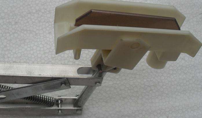
Current collector: It is spring-supported type, which can be pushed in only from the lower part of the sliding contact line, but it must be synchronized with the tractor, and the tension of the tension spring should be appropriate to avoid increasing brush wear. The tractor and current collector are synchronized and can be fixed on the traveling crane or other mobile electrical equipment by bolts or welding, and appropriately ensure that the current collector operates without torsion.
Selection instructions
When selecting this sliding line device, users should consider the total capacity of electrical equipment on the same span of sliding contact line and the working system of the electrical equipment. The above current carrying capacity curve chart is for user reference. When selecting the current collector, consideration should be given to matching the capacity of the electrical equipment with the current collector. When the single-pole capacity of the current collector is insufficient, a double-pole current collector can be used.
Schematic diagram of installation forms
Note: This device generally adopts front installation or side installation. Multiple rows and curved tracks are allowed (the minimum radius of the curve should not be less than 1.5m). The dimensions in brackets are suitable for 200-300A guide rails. The spacing a between L1, L2, L3, and PE is 90mm