I-beam cable trolley
The GHC series I-beam trolley device is used for suspending and moving cables of mobile power supply machinery during movement, and has been widely applied in various types of cranes. This device has advantages such as sturdy structure, flexible movement, and safety and reliability.
The GHC type trolley consists of three parts: the traction trolley, cable trolley, and terminal trolley. The traction trolley follows the cable guiding (traction) device of the mobile machinery, with one per mobile machinery, moving back and forth with it. The intermediate cable trolleys suspend the cable within the range of the I-beam track and move with the traction trolley, with buffer bumpers installed at both ends. The number of trolleys depends on the length of movement. The terminal trolley is fixed at the end of the I-beam guide rail, generally one per mobile machinery.
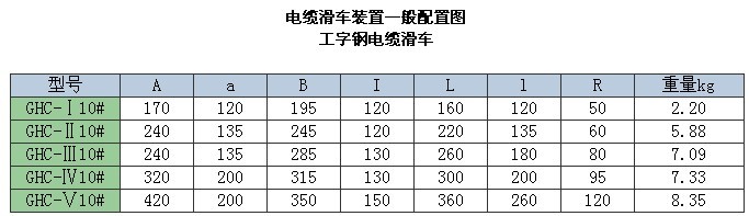
This series of trolleys is divided into five models: I, II, III, IV, and V. If users adopt 12#, 14#, 16#, or larger I-beams, please specify when ordering, and our factory can supply the complete set.
Product Introduction:
The HC series cable trolley is a conductive form for crane trolley power supply. It consists of wheels, brackets, and support plates. The soft cable is fixed on the support plate, and the traction frame moves synchronously with the cable trolley, thereby achieving the purpose of power supply to the trolley.
The HC series cable trolleys are divided into medium load type, heavy load type, and light load type. Therefore, the trolley wheels are of three types: Ф80, Ф63, and Ф50, with a load capacity of ≤50∽150kg. Each type is divided into single-layer, double-layer, and triple-layer according to the number of support plate layers. Each type has three forms: the front end is the cable traction trolley, the terminal end is the fixed cable hanger, and the middle is the cable trolley (see figure below).
II. Description
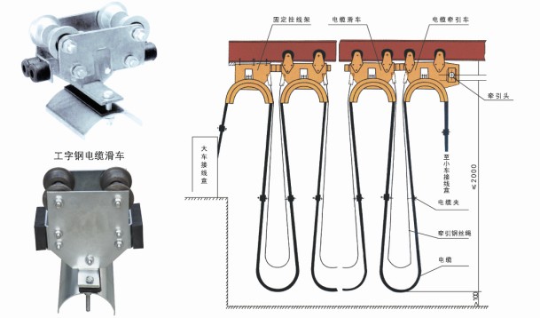
1. After the fixed cable hanger is installed, a baffle should be hung behind it.
2. Adjust the traction head so that the trolley does not touch the upper and lower edges of the traction hole throughout the entire travel.
3. The cable length is 1.2 times the crane span plus 8 meters.
4. Adjust the traction wire rope so that its length is less than the length of the cable in the same section, and the traction wire rope bears the force during operation.
5. When the cable diameters are different, soft rubber should be placed between the cable clamps to make their outer diameters basically the same, so as to clamp the cables tightly.
6. When laying cables, consider the balanced force on the cable support plates on both sides.
7. When the cable trolley has two or three layers, the requirements are the same.
8. The double washers on the trolley device are adjustment washers. When the guide rail is not suitable, place the washers on the inside of the fixed plate to adjust the width of the track gauge. At the factory, they are manufactured according to the guide rails I 100*68*4.5, I 120*74*5, I140*80*5, I 160*88*6. Non-standard trolleys are processed and manufactured according to drawings.
|